

AutoCad2010
New file format "AutoCAD 2010" and is likely to be used for AutoCAD 2011 and AutoCAD 2012. Last file format change was in AutoCAD 2007. The version number is 18.0 and the internal DWG and DXF version is AC1024. It is possible to save to earlier formats down to R14 DWG and R12 DXF.
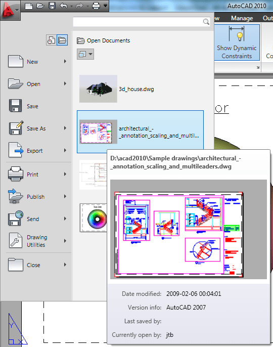
Initial Setup is displayed the first time you start AutoCAD 2010 and allow you to select the industry that most closely describes your work like Architecture or Civil Engineering for example. Depending on your choices the following will be set: the default settings of various AutoCAD functionality, including drawing templates, Autodesk® Seek filters, Autodesk Developer Network partners, the Unified Online Experience portal, and workspaces. If you later want to access Initial Setup it is available via Options>User Preferences.
Application Menu has been changed a lot compared to AutoCAD 2009's Menu Browser. There is no longer access to pull-down menus from here. Some name changes have been done. Publish command is known as Batch Plot and available via the Print menu. The Publish menu have access to Send to 3D Print Service and Archive but if you click directly on the Publish menu the publish command is launched.
The ribbon has been updated. You can drag a ribbon panel off the ribbon to display it as a sticky panel. Sticky panels remain displayed, even when selecting a different tab, until you select the option to Return Panels to Ribbon.
The vertical ribbon has been updated to show the tab names along the side. The panel titles are displayed by default and those with additional tools include slide-out panels. When resizing the vertical ribbon, buttons automatically flow to the next or previous row and other elements, such as slider bars, automatically shorten or lengthen.
Custom dashboard panels can be converted to new ribbon panels using the Transfer tab in the Customize User Interface (CUI) Editor.
You can customize contextual ribbon tab states which control the display of ribbon tabs and panels based on either the type of object selected in the drawing window or the active command. You can display a ribbon tab that is assigned to a ribbon contextual tab state either on its own tab or with its panels merged onto each of the ribbon tabs in the current workspace. To add a ribbon tab, drag it from the Tabs node in the Customizations In pane to the contextual tab state. For example, if you want the Home tab to become active whenever you select an Arc object, drag the Home-2D ribbon tab to the Arc selected node under the Contextual Tab States. Select it and modify its display type to indicate if it should be displayed as its own tab or merged onto each ribbon tab.
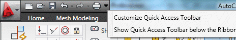
The Quick Access toolbar has been enhanced with more functionality and to ensure consistency with other Windows applications. The Undo and Redo tools include history support and the right-click menu includes new options that enable you to easily remove tools from the toolbar, add separators between tools, and display the Quick Access toolbar above or below the ribbon.
The Quick Access toolbar includes a new flyout menu, which displays a list of common tools that you can select to include in the Quick Access toolbar. The flyout menu provides easy access to additional tools using the Command List pane in the CUI Editor. Other options enable you to show the menu bar or display the Quick Access toolbar below the ribbon.
The Quick Access toolbar can be customized using the new Quick Access toolbars node in the CUI Editor. Multiple versions of the Quick Access toolbar can be created and added to different workspaces.
The New Features Workshop has been updated to include AutoCAD 2010 functionality.
Parametric Drawing
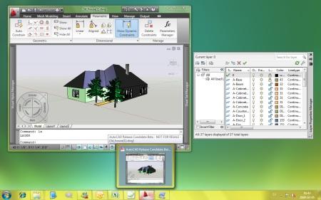
Parametric drawing functionality enables you to constraining drawing objects based on design intent. Geometric and dimensional constraints help ensure that specific relationships and measurements remain persistent even as objects are modified. The tools for creating and managing geometric and dimensional constraints are available on the Parametric ribbon tab, which is automatically displayed in the 2D Drafting and Annotation workspace.
Geometric constraints establish and maintain geometric relationships between objects, key points on objects, or between an object and the coordinate system. Pairs of key points on or between objects can also be constrained to be vertical or horizontal relative to the current coordinate system. For example, you could specify that two circles must always be concentric, that two lines are always parallel, or that one side of a rectangle is always horizontal.
Geometric relationships are defined with geometric constraints, located on the Geometric Panel of the Parametric tab of the ribbon, or with the GEOMCONSTRAINT command. When applying constraints, an icon appears next to the cursor to help you remember which constraint you selected.
When applying a constraint to points, a temporary marker identifies the closest valid point when rolling over an object. It generally corresponds with points that can be used as object snaps.
Whether selecting objects or points on objects to constrain, the order and pick location affects how the objects update: the second object selected updates to satisfy the constraint. After the constraint is applied, though, either object will update when the other is modified.
You can significantly automate the process of applying constraints using the AutoConstrain functionality, available on the Geometric panel of the Parametric tab. AutoConstrain automatically applies constraints to geometry that falls within specified tolerances. For example, applying AutoConstrain to a rectangle consisting of four lines generates the appropriate coincident, horizontal, parallel, and perpendicular constraints to maintain the rectangular shape through various edits. You can control which constraints are available, in what order they are applied, and a tolerance to determine whether constraints are automatically applied. These controls are available on the AutoConstrain tab of the Constraint Settings dialog box, which you can access from the Parametric tab or using the CONSTRAINTSETTINGS command.
Constraint bars show the constraints applied to an object. You can control the display of constraint bars using the CONSTRAINTBAR command or the Show, Show All, and Hide All options on the Geometric panel of the Parametric ribbon tab.
When constraint bars are displayed, you can pass the cursor over a constraint to view the constraint name and the objects that it affects.
You can further control the display of constraint bars on the Geometric tab of the Constraint Settings dialog box. Options include the ability to individually specify which types of constraints can be displayed in the constraint bar, apply transparency, and automatically show the constraint bars after applying constraints to selected objects regardless of the current constraint bar visibility setting.
Establishing Dimensional Relationships
Dimensional relationships put limits on measurements of geometry. For example, you could use a dimensional constraint to specify the radius of an arc, the length of a line, or that two parallel lines are always 15 mm apart. Changing the value of a dimensional constraint forces a change in geometry.
You can create dimensional constraints from the Dimensional panel of the Parametric tab or with the DIMCONSTRAINT command. There are seven types of dimensional constraints, similar to the different kinds of dimensions: Linear, Aligned, Horizontal, Vertical, Angular, Radial, and Diameter. In fact, you can use the DIMCONSTRAINT command to convert a traditional dimension to the corresponding dimensional constraint.
Dimensional constraints are assigned a name when created. The text of a dimensional constraint can display its name, value, or its name and expression (name = formula or equation or value). A “lock” icon appears next to all dimensional constraints to help you visually distinguish them from regular dimensions. By default, dimensional constraints are displayed with a fixed system style that is zoom-invariant—it stays the same size relative to the screen when you zoom in and out so it is always readable.
You can control the display of dimensional constraints, including the visibility of the lock icon, from the Dimensional tab of the Constraint Settings dialog box.
Easily edit a dimensional constraint using grips or by double-clicking on the dimension text to enter values. When you double-click, the constraint name and expression are automatically displayed regardless of the constraint format setting. You can enter just a value, or a name and value using the format name=value (for example, Width=1.5 or Width=Length/3). You can rename dimensional constraints, and use those names in formulas to set the values of other constraints. For example, if you have a rectangle with constraints named “length” and “width,” you could define the value of “width” as “length/3” to constrain the rectangle’s width to 1/3 of its length.
The Parameters Manager, available from the ribbon, enables you to manage dimensional parameters as well as create and manage user-defined parameters. You can provide a meaningful name for the parameter and then assign a numeric value or formula as its expression. A parameter’s expression can reference other parameters so that its value automatically updates when the other parameter values change.
Dimensional constraints can take one of two forms: Annotational or Dynamic. Both forms control geometry in the same way, but they differ in their appearance and they way they are managed.
Dynamic dimensional constraints are not intended to be used as plotted annotation and they have a predefined style that cannot be modified. The display height is controlled by the BPARAMETERSIZE system variable. The visibility of dynamic constraints can be controlled in a variety of ways. First, you can show or hide all dynamic constraints with two icons on the ribbon. Second, even if dynamic constraints are hidden, you can choose to display them when a constrained object is selected, by using the checkbox in the Constraint Settings dialog or the DYNCONSTRAINTMODE system variable. Finally, even if dynamic constraints are set to “Show All,” they will only appear if at least one of the constrained objects is visible (on a layer which is On and Thawed).
Annotational constraints look just like dimension objects, and are managed the same way. They have all the same properties as regular dimensions, including Style. Annotational constraints are intended to be used for plotted dimensional constraints.
You can specify which constraint form is applied by default using the CCONSTRAINTFORM system variable. Additionally, you can specify the constraint form when using the DIMCONSTRAINT command to create a new dimensional constraint. Even after you have created a dimensional constraint, you can easily change its constraint form using the Properties palette.
AutoCAD 2010 running on Windows 7.
pdf :
click here
RapidShare
part 1
part 2
part 3
part 4
part 5
part 6
part 7
part 8
part 9
part 10
part 11
part 12
part 13
part 14
part 15
part 16
part 17

+ إنشاء موضوع جديد
النتائج 1 إلى 10 من 50
الموضوع: AutoCad 2010 للتحميل الان
-
02-18-2009, 08:26 AM #1Status
- Offline

- تاريخ التسجيل
- Sep 2008
- الدولة
- Alexandria, Egypt, Egypt
- المشاركات
- 2,482

 اخصائي مساحة خرائط و نظم معلومات جغرافية
- معدل تقييم المستوى
- 8209
 AutoCad 2010 للتحميل الان

-
02-18-2009, 10:04 PM #2Status
- Offline
- تاريخ التسجيل
- Sep 2008
- العمر
- 35
- المشاركات
- 3,041
عضو ملكى 100%
- معدل تقييم المستوى
- 8852
 ايه ده
مش عارف اقولك ايه حتى كلمه الله ينور قليله على اللى انت عامله
بجد يا ايمن شغل من نار
الله ينور بجد على الشغل ده
بجد فعلا تستحق لقب اصغر استشارى مساحه فى السن على مستوى جمهوريات اسيا الوسطى واسيا والفلطبين
هههههههههههههههه
ربنا يكرمك بجد يا ايمن
مهندس / اسلام ممدوح ابوضيف
مهندس مساحه تركيبات ميكانيكيه
شركه T .Q .C
-
02-19-2009, 09:57 AM #3Status
- Offline
- تاريخ التسجيل
- Sep 2008
- الدولة
- Alexandria, Egypt, Egypt
- المشاركات
- 2,482
اخصائي مساحة خرائط و نظم معلومات جغرافية
- معدل تقييم المستوى
- 8209
-
02-20-2009, 09:42 PM #4Status
- Offline

- تاريخ التسجيل
- Sep 2008
- المشاركات
- 283
اخصائي مساحة و نظم معلومات جغرافية دفعة 2009
- معدل تقييم المستوى
- 5983
-
02-20-2009, 09:44 PM #5Status
- Offline
- تاريخ التسجيل
- Sep 2008
- الدولة
- Alexandria, Egypt, Egypt
- المشاركات
- 2,482
اخصائي مساحة خرائط و نظم معلومات جغرافية
- معدل تقييم المستوى
- 8209
-
03-12-2009, 08:54 PM #6Status
- Offline
- تاريخ التسجيل
- Mar 2009
- المشاركات
- 25
عضو جديد 10%
- معدل تقييم المستوى
- 0
fsfw vdee fdd fdfdffe zvhyre
-
03-12-2009, 08:55 PM #7Status
- Offline
- تاريخ التسجيل
- Mar 2009
- المشاركات
- 25
عضو جديد 10%
- معدل تقييم المستوى
- 0
dervdd rtt sfedfr kktrn s sdw sdff
-
03-12-2009, 08:55 PM #8Status
- Offline
- تاريخ التسجيل
- Mar 2009
- المشاركات
- 25
عضو جديد 10%
- معدل تقييم المستوى
- 0
sxcqe 334h nwrgtr n
-
03-12-2009, 08:56 PM #9Status
- Offline
- تاريخ التسجيل
- Mar 2009
- المشاركات
- 25
عضو جديد 10%
- معدل تقييم المستوى
- 0
dswdgrt3n rt4y3 rt5y532
-
03-12-2009, 08:56 PM #10Status
- Offline
- تاريخ التسجيل
- Mar 2009
- المشاركات
- 25
عضو جديد 10%
- معدل تقييم المستوى
- 0
fgbxdssv wqe23 fr 242


 رد مع اقتباس

المفضلات